Note that attribute names are case-sensitive.
This is usually true for attribute values as well, unless noted.
All Graphviz attributes are specified by name-value pairs. Thus, to
set the fillcolor of a node abc, one would use
- Damping
- Factor damping force motions. On each iteration, a nodes movement
is limited to this factor of its potential motion. By being less than
1.0, the system tends to ``cool'', thereby preventing cycling.
- K
- Spring constant used in virtual physical model. It roughly corresponds
to an ideal edge length (in inches), in that increasing K tends to
increase the distance between nodes.
Note that the edge attribute len can be used to
override this value for adjacent nodes.
- URL
- Hyperlinks incorporated into device-dependent output.
At present, used in ps2, cmap, i*map and svg formats.
For all these formats, URLs can be attached to nodes, edges and
clusters. URL attributes can also be attached to the root graph in ps2,
cmap and i*map formats. This serves as the base URL for relative URLs in the
former, and as the default image map file in the latter.
For svg, cmapx and imap output, the active area for a node is its
visible image.
For example, an unfilled
node with no drawn boundary will only be active on its label.
For other output, the active area is its bounding box.
The active area for a cluster is its bounding box.
For edges, the active areas are small circles where the edge contacts its head
and tail nodes. In addition, for svg, cmapx and imap, the active area
includes a thin polygon approximating the edge. The circles may
overlap the related node, and the edge URL dominates.
If the edge has a label, this will also be active.
Finally, if the edge has a head or tail label, this will also be active.
Note that, for edges, the attributes headURL,
tailURL, labelURL and
edgeURL allow control of various parts of an
edge.
Also note that, if active areas of two edges overlap, it is unspecified
which area dominates.
- _background
- A string in the xdot format specifying an arbitrary background.
During rendering, the canvas is first filled as described in the
bgcolor attribute.
Then, if _background is defined, the graphics
operations described in the string are performed on the canvas.
- area
- Indicates the preferred area for a node or empty cluster when laid out by patchwork.
- arrowhead
- Style of arrowhead on the head node of an edge.
This will only appear if the dir attribute
is "forward" or "both".
See the limitation.
- arrowsize
- Multiplicative scale factor for arrowheads.
- arrowtail
- Style of arrowhead on the tail node of an edge.
This will only appear if the dir attribute
is "back" or "both".
See the limitation.
- bb
- Bounding box of drawing in points.
- bgcolor
- When attached to the root graph, this color is used as the background for
entire canvas. When a cluster attribute, it is used as the initial
background for the cluster. If a cluster has a filled
style, the
cluster's fillcolor will overlay the
background color.
If the value is a colorList, a gradient fill is
used. By default, this is a linear fill; setting style=radial will
cause a radial fill. At present, only two colors are used. If the second
color (after a colon) is missing, the default color is used for it.
See also the gradientangle attribute
for setting the gradient angle.
For certain output formats, such as PostScript, no fill is done for
the root graph unless
bgcolor is explicitly set. For bitmap formats, however,
the bits need to be
initialized to something, so the canvas is filled with white by default.
This means that if the bitmap output is included in some other
document, all of the bits within the bitmap's bounding box will be
set, overwriting whatever color or graphics were already on the page.
If this effect is not desired, and you only want to set bits explicitly
assigned in drawing the graph, set bgcolor="transparent".
- center
- If true, the drawing is centered in the output canvas.
- charset
- Specifies the character encoding used when interpreting string input
as a text label. The default value is "UTF-8".
The other legal value is "iso-8859-1" or,
equivalently,
"Latin1". The charset attribute is case-insensitive.
Note that if the character encoding used in the input does not
match the charset value, the resulting output may be very strange.
- clusterrank
- Mode used for handling clusters. If clusterrank is "local", a
subgraph whose name begins with "cluster" is given special treatment.
The subgraph is laid out separately, and then integrated as a unit into
its parent graph, with a bounding rectangle drawn about it.
If the cluster has a label parameter, this label
is displayed within the rectangle.
Note also that there can be clusters within clusters.
At present, the modes "global" and "none"
appear to be identical, both turning off the special cluster processing.
- color
- Basic drawing color for graphics, not text. For the latter, use the
fontcolor attribute.
For edges, the value
can either be a single color or a colorList.
In the latter case, if colorList has no fractions,
the edge is drawn using parallel splines or lines,
one for each color in the list, in the order given.
The head arrow, if any, is drawn using the first color in the list,
and the tail arrow, if any, the second color. This supports the common
case of drawing opposing edges, but using parallel splines instead of
separately routed multiedges.
If any fraction is used, the colors are drawn in series, with each color
being given roughly its specified fraction of the edge.
For example, the graph
  digraph G {
    a -> b [dir=both color="red:blue"]
    c -> d [dir=none color="green:red;0.25:blue"]
  }
yields

- colorscheme
- This attribute specifies a color scheme namespace. If defined, it specifies
the context for interpreting color names. In particular, if a
color value has form "xxx" or "//xxx",
then the
color xxx will be evaluated according to the current color scheme.
If no color scheme is set, the standard X11 naming is used.
For example, if colorscheme=bugn9, then color=7
is interpreted as "/bugn9/7".
- comment
- Comments are inserted into output. Device-dependent
- compound
- If true, allow edges between clusters. (See lhead
and ltail below.)
- concentrate
- If true, use edge concentrators.
This merges multiedges into a single edge and causes partially parallel
edges to share part of their paths. The latter feature is not yet available
outside of dot.
- constraint
- If false, the edge is not used in ranking the nodes. For example,
in the graph
  digraph G {
    a -> c;
    a -> b;
    b -> c [constraint=false];
  }
the edge b -> c does not add a constraint during rank
assignment, so the only constraints are that a be above b and c,
yielding the graph:
- decorate
- If true, attach edge label to edge by a 2-segment
polyline, underlining the label, then going to the closest point of spline.
- defaultdist
- This specifies the distance between nodes in separate connected
components. If set too small, connected components may overlap.
Only applicable if pack=false.
- dim
- Set the number of dimensions used for the layout. The maximum value
allowed is 10.
- dimen
- Set the number of dimensions used for rendering.
The maximum value allowed is 10.
If both dimen and dim are set, the latter specifies
the dimension used for layout, and the former for rendering.
If only dimen is set, this is used for both layout and rendering
dimensions.
Note that, at present, all aspects of rendering are 2D. This includes
the shape and size of nodes, overlap removal, and edge routing. Thus,
for dimen > 2, the only valid information is the pos
attribute of the nodes.
All other coordinates will be 2D and, at best, will reflect a projection
of a higher-dimensional point onto the plane.
- dir
- Set edge type for drawing arrowheads. This indicates which ends of the
edge should be decorated with an arrowhead. The actual style of the
arrowhead can be specified using the arrowhead
and arrowtail attributes.
See limitation.
- diredgeconstraints
- Only valid when mode="ipsep".
If true, constraints are generated for each edge in the largest (heuristic)
directed acyclic subgraph such that the edge must point downwards.
If "hier", generates level constraints similar to those used with
mode="hier". The main difference is that, in the latter
case, only these constraints are involved, so a faster solver can be used.
- distortion
- Distortion factor for shape=polygon.
Positive values cause top part to
be larger than bottom; negative values do the opposite.
- dpi
- This specifies the expected number of pixels per inch on a display device.
For bitmap output, this guarantees that text rendering will be
done more accurately, both in size and in placement. For SVG output,
it is used to guarantee that the dimensions in the output correspond to
the correct number of points or inches.
- edgeURL
- If edgeURL is defined, this is the link used for the non-label
parts of an edge. This value overrides any URL
defined for the edge.
Also, this value is used near the head or tail node unless overridden
by a headURL or tailURL value,
respectively.
See limitation.
- edgehref
- Synonym for edgeURL.
- edgetarget
- If the edge has a URL or edgeURL
attribute, this attribute determines which window of the
browser is used
for the URL attached to the non-label part of the edge.
Setting it to "_graphviz" will open a new window if it
doesn't already exist, or reuse it if it does.
If undefined, the value of the target is used.
- edgetooltip
- Tooltip annotation attached to the non-label part of an edge.
This is used only if the edge has a URL
or edgeURL attribute.
- epsilon
- Terminating condition. If the length squared of all energy gradients are
< epsilon, the algorithm stops.
- esep
- Margin used around polygons for purposes of spline edge routing.
The interpretation is the same as given for sep.
This should normally be strictly less than sep.
- fillcolor
- Color used to fill the background of a node or cluster
assuming style=filled, or a filled arrowhead.
If fillcolor is not defined, color is
used. (For clusters, if color is not defined,
bgcolor is used.) If this is not defined,
the default is used, except for
shape=point or when the output
format is MIF,
which use black by default.
If the value is a colorList, a gradient fill is
used. By default, this is a linear fill; setting style=radial will
cause a radial fill. At present, only two colors are used. If the second
color (after a colon) is missing, the default color is used for it.
See also the gradientangle attribute
for setting the gradient angle.
Note that a cluster inherits the root graph's attributes if defined.
Thus, if the root graph has defined a fillcolor, this will override a
color or bgcolor attribute set for the cluster.
- fixedsize
- If false, the size of a node is determined by smallest width and height
needed to contain its label and image, if any, with a margin specified by
the margin attribute. The width
and height must also be at least as large as the sizes specified by the
width and
height attributes, which specify
the minimum values for these parameters.
If true, the node size is specified by the values of the
width
and height attributes only
and is not expanded to contain the text label.
There will be a warning if the label (with margin)
cannot fit within these limits.
If the fixedsize attribute is set
to shape, the width and
height attributes also determine the size
of the node shape, but the label can be much larger. Both the label and
shape sizes are used when avoiding node overlap, but all edges to the
node ignore the label and only contact the node shape. No warning is given
if the label is too large.
- fontcolor
- Color used for text.
- fontname
- Font used for text. This very much depends on the output format and, for
non-bitmap output such as PostScript or SVG, the availability of the font
when the graph is displayed or printed. As such, it is best to rely on
font faces that are generally available, such as Times-Roman, Helvetica or
Courier.
How font names are resolved also depends on the underlying library that handles
font name resolution.
If Graphviz was built using the
fontconfig library,
the latter library will be used to search for the font.
See the commands fc-list, fc-match and the other fontconfig commands for how
names are resolved and which fonts are available.
Other systems may provide their own font package, such as Quartz for OS X.
Note that various font attributes, such as weight and slant, can be built into the
font name. Unfortunately, the syntax varies depending on which font system is dominant.
Thus, using fontname="times bold italic" will produce a bold, slanted Times font
using Pango, the usual main font library. Alternatively,
fontname="times:italic" will produce a slanted
Times font from fontconfig, while fontname="times-bold" will resolve to a bold
Times using Quartz. You will need
to ascertain which package is used by your Graphviz system and refer to the relevant
documentation.
If Graphviz is not built with a high-level font library, fontname will be
considered the name of a Type 1 or True Type font file.
If you specify fontname=schlbk, the tool will look for a
file named schlbk.ttf or schlbk.pfa or schlbk.pfb
in one of the directories specified by
the fontpath attribute.
The lookup does support various aliases for the common fonts.
- fontnames
- Allows user control of how basic fontnames are represented in SVG output.
If fontnames is undefined or "svg",
the output will try to use known SVG fontnames. For example, the
default font "Times-Roman" will be mapped to the
basic SVG font "serif". This can be overridden by setting
fontnames to "ps" or "gd".
In the former case, known PostScript font names such as
"Times-Roman" will be used in the output.
In the latter case, the fontconfig font conventions
are used. Thus, "Times-Roman" would be treated as
"Nimbus Roman No9 L". These last two options are useful
with SVG viewers that support these richer fontname spaces.
- fontpath
- Directory list used by libgd to search for bitmap fonts if Graphviz
was not built with the fontconfig library.
If fontpath is not set, the environment
variable DOTFONTPATH is checked.
If that is not set, GDFONTPATH is checked.
If not set, libgd uses its compiled-in font path.
Note that fontpath is an attribute of the root graph.
- fontsize
- Font size, in points, used for text.
- forcelabels
- If true, all xlabel attributes are placed, even if there is some overlap with nodes
or other labels.
- gradientangle
- If a gradient fill is being used, this determines the angle of the fill. For linear fills, the colors transform
along a line specified by the angle and the center of the object. For radial fills, a value of zero causes the
colors to transform radially from the center; for non-zero values, the colors transform from a point near the
object's periphery as specified by the value.
If unset, the default angle is 0.
- group
- If the end points of an edge belong to the same group, i.e., have the
same group attribute, parameters are set to avoid crossings and keep
the edges straight.
- headURL
- If headURL is defined, it is
output as part of the head label of the edge.
Also, this value is used near the head node, overriding any
URL value.
See limitation.
- head_lp
- Position of an edge's head label, in points.
The position indicates the center of the label.
- headclip
- If true, the head of an edge is clipped to the boundary of the head node;
otherwise, the end of the edge goes to the center of the node, or the
center of a port, if applicable.
- headhref
- Synonym for headURL.
- headlabel
- Text label to be placed near head of edge.
See limitation.
- headport
- Indicates where on the head node to attach the head of the edge.
In the default case, the edge is aimed towards the center of the node,
and then clipped at the node boundary.
See limitation.
- headtarget
- If the edge has a headURL,
this attribute determines which window of the
browser is used
for the URL. Setting it to "_graphviz" will open a new window if it
doesn't already exist, or reuse it if it does.
If undefined, the value of the target is used.
- headtooltip
- Tooltip annotation attached to the head of an edge. This is used only
if the edge has a headURL attribute.
- height
- Height of node, in inches. This is taken as the initial, minimum height
of the node. If fixedsize is true, this
will be the final height of the node. Otherwise, if the node label
requires more height to fit, the node's height will be increased to
contain the label. Note also that, if the output format is dot, the
value given to height will be the final value.
If the node shape is regular, the width and height are made identical.
In this case, if either the width or the height is set explicitly,
that value is used.
In this case, if both the width or the height are set explicitly,
the maximum of the two values is used.
If neither is set explicitly, the minimum of the two default values
is used.
- href
- Synonym for URL.
- id
- Allows the graph author to provide an id for graph objects which is to be included in the output.
Normal "\N", "\E", "\G" substitutions are applied.
If provided, it is the responsibility of the provider to keep
its values sufficiently unique for its intended downstream use.
Note, in particular, that "\E" does not provide a unique id for multi-edges.
If no id attribute is provided, then a unique internal id is used. However,
this value is unpredictable by the graph writer.
An externally provided id is not used internally.
If the graph provides an id attribute, this will be used as a prefix for
internally generated attributes. By making these distinct, the user
can include multiple image maps in the same document.
- image
- Gives the name of a file containing an image to be displayed inside
a node. The image file must be in one of the recognized
formats,
typically JPEG, PNG, GIF, BMP, SVG or Postscript, and be able to be converted
into the desired output format.
The file must contain the image size information. This is usually trivially
true for the bitmap formats. For PostScript, the file must contain a
line starting with %%BoundingBox: followed by four integers
specifying the lower left x and y coordinates and the upper right x and y
coordinates of the bounding box for the image, the coordinates being in
points. An SVG image file must contain width and height
attributes, typically as part of the svg element.
The values for these should have the form of a floating point number,
followed by optional units, e.g., width="76pt".
Recognized units are in, px,
pc, pt, cm and mm for inches, pixels,
picas, points, centimeters and millimeters, respectively.
The default unit is points.
Unlike with the shapefile attribute,
the image is treated as node
content rather than the entire node. In particular, an image can
be contained in a node of any shape, not just a rectangle.
- imagepath
- Specifies a list of directories in which to look for image files as specified by the
image attribute or using the IMG element in
HTML-like labels.
The string should be a list of (absolute or relative) pathnames, each separated by
a semicolon (for Windows) or a colon (all other OS).
The first directory in which a file of the given name is found will be used to
load the image. If imagepath is not set, relative pathnames for the image
file will be interpreted with respect to the current working directory.
- imagepos
- Attribute controlling how an image is positioned within its containing node. This
only has an effect when the image is smaller than the containing node. The
default is to be centered both horizontally and vertically. Valid values:
| tl | Top Left |
| tc | Top Centered |
| tr | Top Right |
| ml | Middle Left |
| mc | Middle Centered (the default) |
| mr | Middle Right |
| bl | Bottom Left |
| bc | Bottom Centered |
| br | Bottom Right |
- imagescale
- Attribute controlling how an image fills its
containing node. In general, the image is given its natural size,
(cf. dpi),
and the node size is made large enough to contain its image, its
label, its margin, and its peripheries.
Its width and height will also be at least as large as its
minimum width and height.
If, however, fixedsize=true,
the width and height attributes specify the exact size of the node.
During rendering, in the default case (imagescale=false),
the image retains its natural size.
If imagescale=true,
the image is uniformly scaled (i.e., its aspect ratio is
preserved) to fit inside the node.
At least one dimension of the image will be as large as possible
given the size of the node.
When imagescale=width,
the width of the image is scaled to fill the node width.
The corresponding property holds when imagescale=height.
When imagescale=both,
both the height and the width are scaled separately to fill the node.
In all cases, if a dimension of the image is larger than the
corresponding dimension of the node, that dimension of the
image is scaled down to fit the node. As with the case of
expansion, if imagescale=true, width and height are
scaled uniformly.
- inputscale
- For layout algorithms that support initial input positions (specified by the pos attribute),
this attribute can be used to appropriately scale the values. By default, fdp and neato interpret
the x and y values of pos as being in inches. (NOTE: neato -n(2) treats the coordinates as
being in points, being the unit used by the layout algorithms for the pos attribute.) Thus, if
the graph has pos attributes in points, one should set inputscale=72.
This can also be set on the command line using the -s flag flag.
If not set, no scaling is done and the units on input are treated as inches.
A value of 0 is equivalent to inputscale=72.
- label
- Text label attached to objects.
If a node's shape is record, then the label can
have a special format
which describes the record layout.
Note that a node's default label is "\N", so the node's name or ID becomes
its label. Technically, a node's name can be an HTML string but this will not
mean that the node's label will be interpreted as an HTML-like label. This is
because the node's actual label is an ordinary string, which will be replaced
by the raw bytes stored in the node's name.
To get an HTML-like label, the label attribute value itself must be an HTML string.
- labelURL
- If labelURL is defined, this is the link used for the label
of an edge. This value overrides any URL
defined for the edge.
- label_scheme
- The value indicates
whether to treat a node whose name has the form |edgelabel|* as a special node representing an edge label.
The default (0) produces no effect.
If the attribute is set to 1, sfdp uses a penalty-based method to make that kind of node close to the
center of its neighbor. With a value of 2, sfdp uses a penalty-based method to make that kind of node
close to the old center of its neighbor. Finally, a value of 3 invokes a two-step process of overlap
removal and straightening.
- labelangle
- This, along with labeldistance, determine
where the
headlabel (taillabel) are placed with respect to the head (tail)
in polar coordinates. The origin in the coordinate system is
the point where the edge touches the node. The ray of 0 degrees
goes from the origin back along the edge, parallel to the edge
at the origin.
The angle, in degrees, specifies the rotation from the 0 degree ray,
with positive angles moving counterclockwise and negative angles
moving clockwise.
- labeldistance
- Multiplicative scaling factor adjusting the distance that
the headlabel(taillabel) is from the head(tail) node.
The default distance is 10 points. See labelangle
for more details.
- labelfloat
- If true, allows edge labels to be less constrained in position.
In particular, it may appear on top of other edges.
- labelfontcolor
- Color used for headlabel and taillabel.
If not set, defaults to edge's fontcolor.
- labelfontname
- Font used for headlabel and taillabel.
If not set, defaults to edge's fontname.
- labelfontsize
- Font size, in points, used for headlabel and taillabel.
If not set, defaults to edge's fontsize.
- labelhref
- Synonym for labelURL.
- labeljust
- Justification for cluster labels. If "r", the label
is right-justified within bounding rectangle; if "l", left-justified;
else the label is centered.
Note that a subgraph inherits attributes from its parent. Thus, if
the root graph sets labeljust to "l", the subgraph inherits
this value.
- labelloc
- Vertical placement of labels for nodes, root graphs and clusters.
For graphs and clusters, only "t" and "b" are allowed, corresponding
to placement at the top and bottom, respectively.
By default, root
graph labels go on the bottom and cluster labels go on the top.
Note that a subgraph inherits attributes from its parent. Thus, if
the root graph sets labelloc to "b", the subgraph inherits
this value.
For nodes, this attribute is used only when the height of the node
is larger than the height of its label.
If labelloc is set to "t", "c", or "b", the label is aligned
with the top, centered, or aligned with the bottom of the node, respectively.
In the default case, the label is vertically centered.
- labeltarget
- If the edge has a URL or labelURL
attribute, this attribute determines which window of the
browser is used
for the URL attached to the label.
Setting it to "_graphviz" will open a new window if it
doesn't already exist, or reuse it if it does.
If undefined, the value of the target is used.
- labeltooltip
- Tooltip annotation attached to label of an edge.
This is used only if the edge has a URL
or labelURL attribute.
- landscape
- If true, the graph is rendered in landscape mode. Synonymous with
rotate=90 or
orientation=landscape.
- layer
- Specifies layers in which the node, edge or cluster is present.
- layerlistsep
- Specifies the separator characters used to split
an attribute of type layerRange into a list of ranges.
- layers
- Specifies a linearly ordered list of layer names attached to the graph
The graph is then output in separate layers. Only those components
belonging to the current output layer appear. For more information,
see the page How to use drawing layers (overlays).
- layerselect
- Selects a list of layers to be emitted.
- layersep
- Specifies the separator characters used to split the
layers attribute into a list of layer names.
- layout
- Specifies the name of the layout algorithm to use, such as "dot"
or "neato". Normally, graphs should be kept independent of a type of
layout. In some cases, however, it can be convenient to embed the type
of layout desired within the graph. For example, a graph containing
position information from a layout might want to record what the
associated layout algorithm was.
This attribute takes precedence over
the -K flag
or the actual command name used.
- len
- Preferred edge length, in inches.
- levels
- Number of levels allowed in the multilevel scheme.
- levelsgap
- Specifies strictness of level constraints in neato
when mode="ipsep" or "hier".
Larger positive values mean stricter constraints, which demand more
separation between levels. On the other hand, negative values will relax
the constraints by allowing some overlap between the levels.
- lhead
- Logical head of an edge. When compound is true,
if lhead is defined and is the name of a cluster containing
the real head,
the edge is clipped to the boundary of the cluster.
See limitation.
- lheight
- Height of graph or cluster label, in inches.
- lp
- Label position, in points.
The position indicates the center of the label.
- ltail
- Logical tail of an edge. When compound is true,
if ltail is defined and is the name of a cluster
containing the real tail,
the edge is clipped to the boundary of the cluster.
See limitation.
- lwidth
- Width of graph or cluster label, in inches.
- margin
- For graphs, this sets x and y margins of canvas, in inches. If the margin
is a single double, both margins are set equal to the given value.
Note that the margin is not part of the drawing but just empty space
left around the drawing. It basically corresponds to a translation of
drawing, as would be necessary to center a drawing on a page. Nothing
is actually drawn in the margin. To actually extend the background of
a drawing, see the pad attribute.
For clusters, this specifies the space between the nodes in the cluster and
the cluster bounding box. By default, this is 8 points.
For nodes, this attribute specifies space left around the node's label.
By default, the value is 0.11,0.055.
- maxiter
- Sets the number of iterations used.
- mclimit
- Multiplicative scale factor used to alter the MinQuit (default = 8)
and MaxIter (default = 24) parameters used during crossing
minimization. These correspond to the
number of tries without improvement before quitting and the
maximum number of iterations in each pass.
- mindist
- Specifies the minimum separation between all nodes.
- minlen
- Minimum edge length (rank difference between head and tail).
- mode
- Technique for optimizing the layout. For neato, if mode is "major",
neato uses stress majorization. If mode is "KK",
neato uses a version of the gradient descent method. The only advantage
to the latter technique is that it is sometimes appreciably faster for
small (number of nodes < 100) graphs. A significant disadvantage is that
it may cycle.
There are two experimental modes in neato, "hier", which adds a top-down
directionality similar to the layout used in dot, and "ipsep", which
allows the graph to specify minimum vertical and horizontal distances
between nodes. (See the sep attribute.)
For sfdp, the default mode is "spring", which corresponds to using
a spring-electrical model. Setting mode to "maxent" causes a similar
model to be run but one that also takes into account edge lengths specified by the
"len" attribute.
- model
- This value specifies how the distance matrix is computed for the input
graph. The distance matrix specifies the ideal distance between every
pair of nodes. neato attemps to find a layout which best achieves
these distances. By default, it uses the length of the shortest path,
where the length of each edge is given by its len
attribute. If model is "circuit", neato uses the
circuit resistance
model to compute the distances. This tends to emphasize clusters. If
model is "subset", neato uses the subset model. This sets the
edge length to be the number of nodes that are neighbors of exactly one
of the end points, and then calculates the shortest paths. This helps
to separate nodes with high degree.
For more control of distances, one can use model=mds. In this
case, the len of an edge is used as the ideal distance
between its vertices. A shortest path calculation is only used for
pairs of nodes not connected by an edge. Thus, by supplying a complete
graph, the input can specify all of the relevant distances.
- mosek
- If Graphviz is built with MOSEK defined, mode=ipsep and mosek=true,
the Mosek software (www.mosek.com) is use to solve the ipsep constraints.
- newrank
- The original ranking algorithm in dot is recursive on clusters. This can produce fewer ranks
and a more compact layout, but sometimes at the cost of a head node being place on a higher
rank than the tail node. It also assumes that a node is not constrained in separate,
incompatible subgraphs. For example, a node cannot be in a cluster and also be constrained by
rank=same with a node not in the cluster.
If newrank=true, the ranking algorithm does a single global ranking, ignoring clusters.
This allows nodes to be subject to multiple constraints. Rank constraints will usually take
precedence over edge constraints.
- nodesep
- In dot, this specifies the minimum space between two adjacent nodes in the same rank, in inches.
For other layouts, this affects the spacing between loops on a single node, or multiedges between
a pair of nodes.
- nojustify
- By default, the justification of multi-line labels is done within the
largest context that makes sense. Thus, in the label of a polygonal
node, a left-justified line will align with the left side of the node
(shifted by the prescribed margin).
In record nodes, left-justified
line will line up with the left side of the enclosing column of fields.
If nojustify is "true", multi-line labels will be justified
in the context of itself. For example, if the attribute is set,
the first label line is long, and the second is shorter and left-justified,
the second will align with the left-most character in the first line,
regardless of how large the node might be.
- normalize
- If set, normalize coordinates of final
layout so that the first point is at the origin, and then rotate the
layout so that the angle of the first edge is specified by the value of normalize in degrees.
If normalize is not a number, it is evaluated as a bool, with true
corresponding to 0 degrees. NOTE: Since the attribute is evaluated first as a number,
0 and 1 cannot be used for false and true.
- notranslate
- By default, the final layout is translated so that the lower-left corner of the bounding box is
at the origin. This can be annoying if some nodes are pinned or if the user runs neato -n.
To avoid this translation, set notranslate to true.
- nslimit
,
- nslimit1
- Used to set number of iterations in
network simplex applications. nslimit is used in
computing node x coordinates, nslimit1 for ranking nodes.
If defined, # iterations = nslimit(1) * # nodes;
otherwise, # iterations = MAXINT.
- ordering
- If the value of the attribute is "out", then
the outedges of a node, that is, edges with the node as its tail node,
must appear
left-to-right in the same order in which they are defined in
the input.
If the value of the attribute is "in", then
the inedges of a node must appear
left-to-right in the same order in which they are defined in
the input.
If defined as a graph or subgraph attribute, the value is applied to all nodes
in the graph or subgraph. Note that the graph attribute takes
precedence over the node attribute.
- orientation
- Angle, in degrees, used to rotate polygon node shapes. For any number of polygon sides, 0 degrees rotation results in a flat base.
- orientation
- If "[lL]*", set graph orientation to landscape
Used only if rotate is not defined.
- outputorder
- Specify order in which nodes and edges are drawn.
- overlap
- Determines if and how node overlaps should be removed. Nodes are first
enlarged using the sep attribute.
If "true" , overlaps are retained.
If the value is "scale", overlaps are removed by uniformly scaling in x and y.
If the value converts to "false", and it is available, Prism, a proximity graph-based algorithm, is
used to remove node overlaps.
This can also be invoked explicitly with "overlap=prism".
This technique starts with a
small scaling up, controlled by the
overlap_scaling attribute,
which can remove a significant portion of the overlap.
The prism option also accepts an optional non-negative integer suffix.
This can be used to control the number of attempts made at overlap
removal. By default, overlap="prism" is equivalent to
overlap="prism1000". Setting overlap="prism0"
causes only the scaling phase to be run.
If Prism is not available, or the version of Graphviz is earlier than 2.28, "overlap=false"
uses a Voronoi-based technique.
This can always be invoked explicitly with "overlap=voronoi".
If the value is "scalexy", x and y are separately
scaled to remove overlaps.
If the value is "compress", the layout will be scaled down as much as
possible without introducing any overlaps, obviously assuming there are
none to begin with.
N.B.The remaining allowed values of overlap
correspond to algorithms which, at present, can produce bad aspect ratios.
In addition, we deprecate the use of the "ortho*" and "portho*".
If the value is "vpsc", overlap removal is done as a
quadratic optimization to minimize node displacement while removing
node overlaps.
If the value is "orthoxy" or "orthoyx", overlaps
are moved by optimizing two constraint problems, one for the x axis and
one for the y. The suffix indicates which axis is processed first.
If the value is "ortho", the technique is similar to "orthoxy" except a
heuristic is used to reduce the bias between the two passes.
If the value is "ortho_yx", the technique is the same as "ortho", except
the roles of x and y are reversed.
The values "portho", "porthoxy", "porthoxy", and "portho_yx" are similar
to the previous four, except only pseudo-orthogonal ordering is
enforced.
If the layout is done by neato with mode="ipsep",
then one can use overlap=ipsep.
In this case, the overlap removal constraints are
incorporated into the layout algorithm itself.
N.B. At present, this only supports one level of clustering.
Except for fdp and sfdp, the layouts assume overlap="true" as the default.
Fdp first uses a number of passes using a built-in, force-directed technique
to try to remove overlaps. Thus, fdp accepts overlap with an integer
prefix followed by a colon, specifying the number of tries. If there is
no prefix, no initial tries will be performed. If there is nothing following
a colon, none of the above methods will be attempted. By default, fdp
uses overlap="9:prism". Note that overlap="true",
overlap="0:true" and overlap="0:" all turn off all overlap
removal.
By default, sfdp uses overlap="prism0".
Except for the Voronoi and prism methods, all of these transforms preserve the
orthogonal ordering of the original layout. That is, if the x coordinates
of two nodes are originally the same, they will remain the same, and if
the x coordinate of one node is originally less than the x coordinate of
another, this relation will still hold in the transformed layout. The
similar properties hold for the y coordinates.
This is not quite true for the "porth*" cases. For these, orthogonal
ordering is only preserved among nodes related by an edge.
- overlap_scaling
- When overlap=prism, the layout is scaled by this factor, thereby
removing a fair amount of node overlap, and making node overlap removal
faster and better able to retain the graph's shape.
If overlap_scaling is negative, the layout is scaled by
-1*overlap_scaling times the average label size.
If overlap_scaling is positive, the layout is scaled by
overlap_scaling.
If overlap_scaling is zero, no scaling is done.
- overlap_shrink
- If true, the overlap removal algorithm will perform a compression pass to reduce the
size of the layout.
- pack
- This is true if the value of pack is "true" (case-insensitive) or a
non-negative integer. If true, each connected component of the graph is
laid out separately, and then the graphs are packed together.
If pack has an integral value, this is used as the size,
in points, of
a margin around each part; otherwise, a default margin of 8 is used.
If pack is interpreted as false, the entire graph is laid out together.
The granularity and method of packing is influenced by the
packmode attribute.
For layouts which always do packing, such a twopi, the pack
attribute is just used to set the margin.
- packmode
- This indicates how connected components should be packed
(cf. packMode). Note that defining
packmode will automatically turn on packing as though one had
set pack=true.
- pad
- The pad attribute specifies how much, in inches, to extend the
drawing area around the minimal area needed to draw the graph.
If the pad is a single double, both the x and y pad values are set
equal to the given value. This area is part of the
drawing and will be filled with the background color, if appropriate.
Normally, a small pad is used for aesthetic reasons, especially when
a background color is used, to avoid having nodes and edges abutting
the boundary of the drawn region.
- page
- Width and height of output pages, in inches. If only a single value
is given, this is used for both the width and height.
If this is set and is
smaller than the size of the layout, a rectangular array of pages of
the specified page size is overlaid on the layout, with origins
aligned in the lower-left corner, thereby partitioning the layout
into pages. The pages are then produced one at a time, in
pagedir order.
At present, this only works for PostScript output. For other types of
output, one should use another tool to split the output into multiple
output files. Or use the viewport to generate
multiple files.
- pagedir
- If the page attribute is set and applicable,
this attribute specifies the order in which the pages are emitted.
This is limited to one of the 8 row or column major orders.
- pencolor
- Color used to draw the bounding box around a cluster.
If pencolor is not defined, color is
used. If this is not defined, bgcolor is used.
If this is not defined, the default is used.
Note that a cluster inherits the root graph's attributes if defined.
Thus, if the root graph has defined a pencolor, this will override a
color or bgcolor attribute set for the cluster.
- penwidth
- Specifies the width of the pen, in points, used to draw lines and curves,
including the boundaries of edges and clusters. The value is inherited
by subclusters.
It has no effect on text.
Previous to 31 January 2008, the effect of penwidth=W
was achieved by including setlinewidth(W)
as part of a style specification.
If both are used, penwidth will be used.
- peripheries
- Set number of peripheries used in polygonal shapes and cluster
boundaries. Note that
user-defined shapes are treated as a
form of box shape, so the default
peripheries value is 1 and the user-defined shape will be drawn in
a bounding rectangle. Setting peripheries=0 will turn this off.
Also, 1 is the maximum peripheries value for clusters.
- pin
- If true and the node has a pos attribute on input, neato or fdp prevents the
node from moving from the input position. This property can also be specified
in the pos attribute itself (cf. the point type).
Note: Due to an artifact of the implementation,
previous to 27 Feb 2014, final coordinates
are translated to the origin. Thus, if you look at the output coordinates
given in the (x)dot or plain format, pinned nodes will not have the same
output coordinates as were given on input. If this is important, a
simple workaround is to maintain the coordinates of a pinned node. The vector
difference between the old and new coordinates will give the translation,
which can then be subtracted from all of the appropriate coordinates.
After 27 Feb 2014, this translation can be avoided in neato by setting the
notranslate to TRUE. However, if the graph
specifies node overlap removal or a change in
aspect ratio, node coordinates may still change.
- pos
- Position of node, or spline control points.
For nodes, the position indicates the center of the node.
On output, the coordinates are in points.
In neato and fdp, pos can be used to set the initial position of a node.
By default, the coordinates are assumed to be in inches. However, the
-s command line flag can be used to specify
different units. As the output coordinates are in points,
feeding the output of a graph laid out by a Graphviz program into
neato or fdp will almost always require the -s flag.
When the -n command line flag is used with
neato, it is assumed the positions have been set by one of the layout
programs, and are therefore in points. Thus, neato -n can accept
input correctly without requiring a -s flag and, in fact,
ignores any such flag.
- quadtree
- Quadtree scheme to use.
A TRUE bool value corresponds to "normal";
a FALSE bool value corresponds to "none".
As a slight exception to the normal interpretation of bool,
a value of "2" corresponds to "fast".
- quantum
- If quantum > 0.0, node label dimensions
will be rounded to integral multiples of the quantum.
- rank
- Rank constraints on the nodes in a subgraph.
If rank="same", all nodes are placed on the same rank.
If rank="min", all nodes are placed on the minimum rank.
If rank="source", all nodes are placed on the minimum rank, and
the only nodes on the minimum rank belong to some subgraph whose
rank attribute is "source" or "min".
Analogous criteria hold for rank="max" and rank="sink".
(Note: the
minimum rank is topmost or leftmost, and the maximum rank is bottommost
or rightmost.)
- rankdir
- Sets direction of graph layout. For example, if rankdir="LR",
and barring cycles, an edge
T -> H; will go
from left to right. By default, graphs are laid out from top to bottom.
This attribute also has a side-effect in determining how record nodes
are interpreted. See record shapes.
- ranksep
- In dot, this gives the desired rank separation, in inches. This is
the minimum vertical distance between the bottom of the nodes in one
rank and the tops of nodes in the next. If the value
contains "equally", the centers of all ranks are spaced equally apart.
Note that both
settings are possible, e.g., ranksep = "1.2 equally".
In twopi, this attribute specifies the radial separation of concentric circles.
For twopi, ranksep can also be a list of doubles. The first double specifies
the radius of the inner circle; the second double specifies the increase in
radius from the first circle to the second; etc. If there are more circles than
numbers, the last number is used as the increment for the remainder.
- ratio
- Sets the aspect ratio (drawing height/drawing width) for the drawing.
Note that this is adjusted before
the size attribute constraints are enforced.
In addition, the calculations usually ignore the node sizes, so the
final drawing size may only approximate what is desired.
If ratio is numeric, it is taken as the desired aspect ratio.
Then, if the actual aspect ratio is less than the desired ratio,
the drawing height is scaled up to achieve the
desired ratio; if the actual ratio is greater than that desired ratio,
the drawing width is scaled up.
If ratio = "fill" and the size
attribute is set, node positions are scaled, separately in both x
and y, so that the final drawing exactly fills the specified size.
If both size values exceed the width
and height of the drawing, then both coordinate values of each
node are scaled up accordingly. However, if either size dimension
is smaller than the corresponding dimension in the drawing, one
dimension is scaled up so that the final drawing has the same aspect
ratio as specified by size.
Then, when rendered, the layout will be
scaled down uniformly in both dimensions to fit the given
size, which may cause nodes and text
to shrink as well. This may not be what the user
wants, but it avoids the hard problem of how to reposition the
nodes in an acceptable fashion to reduce the drawing size.
If ratio = "compress" and the size
attribute is set, dot attempts to compress the initial layout to fit
in the given size. This achieves a tighter packing of nodes but
reduces the balance and symmetry. This feature only works in dot.
If ratio = "expand", the size
attribute is set, and both the width and the height of the graph are
less than the value in size, node positions are scaled
uniformly until at least
one dimension fits size exactly.
Note that this is distinct from using size as the
desired size, as here the drawing is expanded before edges are generated and
all node and text sizes remain unchanged.
If ratio = "auto", the page
attribute is set and the graph cannot be drawn on a single page,
then size is set to an ``ideal'' value.
In particular, the size in a given dimension will be the smallest integral
multiple of the page size in that dimension which is at least half the
current size. The two dimensions are then scaled independently to the
new size. This feature only works in dot.
- rects
- Rectangles for fields of records, in points.
- regular
- If true, force polygon to be regular, i.e., the vertices of the
polygon will lie on a circle whose center is the center of the node.
- remincross
- If true and there are multiple clusters, run crossing
minimization a second time.
- repulsiveforce
- The power of the repulsive force used in an extended Fruchterman-Reingold
force directed model. Values larger than 1 tend to reduce
the warping effect at the expense of less clustering.
- resolution
- This is a synonym for the dpi attribute.
- root
- This specifies nodes to be used as the center of the
layout and the root of the generated spanning tree. As a graph attribute,
this gives the name of the node. As a node attribute, it
specifies that the node should be used as a central node. In twopi,
this will actually be the central node. In circo, the block containing
the node will be central in the drawing of its connected component.
If not defined,
twopi will pick a most central node, and circo will pick a random node.
If the root attribute is defined as the empty string, twopi will reset it
to name of the node picked as the root node.
For twopi, it is possible to have multiple roots, presumably one for each
component. If more than one node in a component is marked as the root, twopi
will pick one.
- rotate
- If 90, set drawing orientation to landscape.
- rotation
- Causes the final layout to be rotated counter-clockwise by the specified number of degrees.
- samehead
- Edges with the same head and the same samehead value are aimed
at the same point on the head. This has no effect on loops.
Each node can have at most 5 unique samehead values.
See limitation.
- sametail
- Edges with the same tail and the same sametail value are aimed
at the same point on the tail. This has no effect on loops.
Each node can have at most 5 unique sametail values.
See limitation.
- samplepoints
- If the input graph defines the vertices
attribute, and output is dot or xdot, this gives
the number of points used for a node whose shape is a circle or ellipse.
It plays the same role in neato, when adjusting the layout to avoid
overlapping nodes, and in image maps.
- scale
- If set, after the initial layout, the layout is scaled by the given factors.
If only a single number is given, this is used for both factors.
- searchsize
- During network simplex, maximum number of edges with negative cut values
to search when looking for one with minimum cut value.
- sep
- Specifies margin to leave around nodes when removing node overlap.
This guarantees a minimal non-zero distance between nodes.
If the attribute begins with a plus sign '+', an additive margin is
specified. That is, "+w,h" causes the node's bounding box to be increased
by w
points on the left and right sides, and by h points on the top and bottom.
Without a plus sign, the node is scaled by 1 + w in the x coordinate
and 1 + h in the y coordinate.
If only a single number is given, this is used for both dimensions.
If unset but esep is defined, the sep values
will be set to the esep values divided by 0.8.
If esep is unset, the default value is used.
- shape
- Set the shape of a node.
- shapefile
- (Deprecated) If defined, shapefile specifies a file containing user-supplied node content.
The shape of the node is set to box.
The image in the shapefile must be
rectangular. The image formats supported as well as the precise semantics of
how the file is used depends on the
output format. For further details, see
Image Formats and
External PostScript files.
There is one exception to this usage.
If shape is set to "epsf", shapefile gives
a filename containing a definition of the node in PostScript.
The graphics defined must be contain all of the
node content, including any desired boundaries.
For further details, see
External PostScript files.
- showboxes
- Print guide boxes in PostScript at the beginning of
routesplines if 1, or at the end if 2. (Debugging)
- sides
- Number of sides if shape=polygon.
- size
- Maximum width and height of drawing, in inches.
If only a single number is given, this is used for both the width
and the height.
If defined and the drawing is larger than the given size,
the drawing is uniformly
scaled down so that it fits within the given size.
If size ends in an exclamation point (!),
then it is taken to be
the desired size. In this case, if both dimensions of the drawing are
less than size, the drawing is scaled up uniformly until at
least one dimension equals its dimension in size.
Note that there is some interaction between the size and
ratio attributes.
- skew
- Skew factor for shape=polygon. Positive values
skew top of polygon to right; negative to left.
- smoothing
- Specifies a post-processing step used to smooth out an uneven distribution
of nodes.
- sortv
- If packmode indicates an array packing,
this attribute specifies an
insertion order among the components, with smaller values inserted first.
- splines
- Controls how, and if, edges are represented. If true, edges are drawn as
splines routed around nodes; if false, edges are drawn as line segments.
If set to none or "", no edges are drawn at all.
(1 March 2007) The values line and spline can be
used as synonyms for false and true, respectively.
In addition, the value polyline specifies that edges should be
drawn as polylines.
(28 Sep 2010) The value ortho specifies edges should be
routed as polylines of axis-aligned segments. Currently, the routing
does not handle ports or, in dot, edge labels.
(25 Sep 2012) The value curved specifies edges should be
drawn as curved arcs.
| 
|
splines=none
splines=""
| splines=line
splines=false
|

| 
|
| splines=polyline
| splines=curved
|

| 
|
| splines=ortho
| splines=spline
splines=true
|
By default, the attribute is unset. How this is interpreted depends on
the layout. For dot, the default is to draw edges as splines. For all
other layouts, the default is to draw edges as line segments. Note that
for these latter layouts, if splines="true", this
requires non-overlapping nodes (cf. overlap).
If fdp is used for layout and splines="compound", then the edges are
drawn to avoid clusters as well as nodes.
- start
- Parameter used to determine the initial layout of nodes. If unset, the
nodes are randomly placed in a unit square with
the same seed is always used for the random number generator, so the
initial placement is repeatable.
- style
- Set style information for components of the graph. For cluster subgraphs, if style="filled", the
cluster box's background is filled.
If the default style attribute has been set for a component, an individual component can use
style="" to revert to the normal default. For example, if the graph has
edge [style="invis"]
making all edges invisible, a specific edge can overrride this via:
a -> b [style=""]
Of course, the component can also explicitly set its style attribute to the desired value.
- stylesheet
- A URL or pathname specifying an XML style sheet, used in SVG output.
- tailURL
- If tailURL is defined, it is
output as part of the tail label of the edge.
Also, this value is used near the tail node, overriding any
URL value.
See limitation.
- tail_lp
- Position of an edge's tail label, in points.
The position indicates the center of the label.
- tailclip
- If true, the tail of an edge is clipped to the boundary of the tail node;
otherwise, the end of the edge goes to the center of the node, or the
center of a port, if applicable.
- tailhref
- Synonym for tailURL.
- taillabel
- Text label to be placed near tail of edge.
See limitation.
- tailport
- Indicates where on the tail node to attach the tail of the edge.
See limitation.
- tailtarget
- If the edge has a tailURL,
this attribute determines which window of the
browser is used
for the URL. Setting it to "_graphviz" will open a new window if it
doesn't already exist, or reuse it if it does.
If undefined, the value of the target is used.
- tailtooltip
- Tooltip annotation attached to the tail of an edge. This is used only
if the edge has a tailURL attribute.
- target
- If the object has a URL, this attribute determines which window
of the browser is used for the URL.
See W3C documentation.
- tooltip
- Tooltip annotation attached to the node or edge. If unset, Graphviz
will use the object's label if defined.
Note that if the label is a record specification or an HTML-like
label, the resulting tooltip may be unhelpful. In this case, if
tooltips will be generated, the user should set a tooltip
attribute explicitly.
- truecolor
- If set explicitly to true or false, the value determines whether or not
internal bitmap rendering relies on a truecolor color model or uses
a color palette.
If the attribute is unset, truecolor is not used
unless there is a shapefile property
for some node in the graph.
The output model will use the input model when possible.
Use of color palettes results in less memory usage during creation of the
bitmaps and smaller output files.
Usually, the only time it is necessary to specify the truecolor model
is if the graph uses more than 256 colors.
However, if one uses bgcolor=transparent with
a color palette, font
antialiasing can show up as a fuzzy white area around characters.
Using truecolor=true avoids this problem.
- vertices
- If the input graph defines this attribute, the node is polygonal,
and output is dot or xdot, this attribute provides the
coordinates of the vertices of the node's polygon, in inches.
If the node is an ellipse or circle, the
samplepoints attribute affects
the output.
- viewport
- Clipping window on final drawing. Note that this attribute supersedes any
size attribute. The width and height of the viewport specify
precisely the final size of the output.
- voro_margin
- Factor to scale up drawing to allow margin for expansion in
Voronoi technique. dim' = (1+2*margin)*dim.
- weight
- Weight of edge. In dot, the heavier the weight, the shorter,
straighter and more vertical the edge is.
N.B. Weights in dot must be integers.
For twopi, a weight of 0 indicates the edge should not be used in constructing a
spanning tree from the root.
For other layouts, a larger weight encourages the layout to
make the edge length closer to that specified by the
len attribute.
- width
- Width of node, in inches. This is taken as the initial, minimum width
of the node. If fixedsize is true, this
will be the final width of the node. Otherwise, if the node label
requires more width to fit, the node's width will be increased to
contain the label. Note also that, if the output format is dot, the
value given to width will be the final value.
If the node shape is regular, the width and height are made identical.
In this case, if either the width or the height is set explicitly,
that value is used.
In this case, if both the width or the height are set explicitly,
the maximum of the two values is used.
If neither is set explicitly, the minimum of the two default values
is used.
- xdotversion
- For xdot output, if this attribute is set, this determines the version of xdot used in output.
If not set, the attribute will be set to the xdot version used for output.
- xlabel
- External label for a node or edge. For nodes, the label will be placed outside of the
node but near it. For edges, the label will be placed near the center of the edge.
This can be useful in dot to avoid the occasional problem when the use of edge labels
distorts the layout. For other layouts, the xlabel attribute can be viewed as a synonym
for the label attribute.
These labels are added after all nodes and edges have been placed. The labels will be placed
so that they do not overlap any node or label. This means it may not be possible to place all
of them. To force placing all of them, use the forcelabels attribute.
- xlp
- Position of an exterior label, in points.
The position indicates the center of the label.
- z
- Deprecated:Use pos attribute, along
with dimen and/or dim
to specify dimensions.
Provides z coordinate value for 3D layouts and displays. If the
graph has dim set to 3 (or more),
neato will use a node's z value
for the z coordinate of its initial position if
its pos attribute is also defined.
Even if no z values are specified in the input, it is necessary to
declare a z attribute for nodes, e.g, using node[z=""]
in order to get z values on output.
Thus, setting dim=3 but not declaring z will
cause neato -Tvrml to
layout the graph in 3D but project the layout onto the xy-plane
for the rendering. If the z attribute is declared, the final rendering
will be in 3D.
- addDouble
A double with an optional prefix '+'.
- addPoint
A point with an optional prefix '+'.
- arrowType
| "normal" | 
| "inv" |  |
| "dot" | 
| "invdot" |  |
| "odot" | 
| "invodot" |  |
| "none" | 
| "tee" |  |
| "empty" | 
| "invempty" |  |
| "diamond" | 
| "odiamond" |  |
| "ediamond" | 
| "crow" |  |
| "box" | 
| "obox" |  |
| "open" | 
| "halfopen" |  |
| "vee" |
| "circle" |  |
These are the basic set of backward-compatible arrow shapes. In addition,
there is a grammar of arrow shapes
which can be used to describe a collection of 2,313,441 arrow combinations of the
39 variations of the primitive set of 10 arrows. The basic arrows shown
above contain all of the primitive shapes
(box, crow, circle, diamond,
dot, inv, none,
normal, tee, vee)
plus ones that can be derived from the grammar
(odot, invdot, invodot,
obox, odiamond)
plus some supported as special cases for backward-compatibility
(ediamond, open, halfopen,
empty, invempty).
- clusterMode
- "local","global","none"
- color
- Colors can be specified using one of four formats.
| "#%2x%2x%2x" | Red-Green-Blue (RGB) |
| "#%2x%2x%2x%2x" | Red-Green-Blue-Alpha (RGBA) |
| "H[, ]+S[, ]+V" | Hue-Saturation-Value (HSV) 0.0 <= H,S,V <= 1.0 |
| string | color name |
The specification for the RGB and RGBA formats are the format strings used by
sscanf to scan the color value. Thus, these values have the form
"#RGB" or "#RGBA", where R, G, B, and A each consist of 2 hexadecimal
digits, and can be separated by whitespace. HSV colors have the form of 3
numbers between 0 and 1, separated by whitespace or commas.
String-valued color specifications are case-insensitive and interpreted
in the context of the current color scheme, as specified by the
colorscheme attribute. If this is undefined,
the X11 naming scheme will be used.
An initial "/" character can be used to override the use of
the colorscheme attribute. In particular, a single initial
"/" will cause the string to be evaluated using the default
X11 naming. If the color value has the form "/ssss/yyyy",
the name yyyy is interpreted using the schema ssss.
If the color scheme name is empty, i.e., the color has the
form "//yyyy", the colorscheme attribute is used.
Thus, the forms "yyyy" and "//yyyy" are
equivalent.
At present, Graphviz recognizes the default color scheme X11,
and the Brewer color schemes (cf. ColorBrewer). Please note that Brewer
color schemes are covered by this license.
Examples:
| Color | RGB | HSV | String |
|---|
| White | "#ffffff" | "0.000 0.000 1.000" | "white" |
| Black | "#000000" | "0.000 0.000 0.000" | "black" |
| Red | "#ff0000" | "0.000 1.000 1.000" | "red" |
| Turquoise | "#40e0d0" | "0.482 0.714 0.878" | "turquoise" |
| Sienna | "#a0522d" | "0.051 0.718 0.627" | "sienna" |
The string value transparent can be used to indicate no color.
This is only available in the output formats
ps, svg, fig, vmrl, and the bitmap formats. It can be used whenever a
color is needed but is most useful with
the bgcolor attribute.
Usually, the same effect can be achieved by setting
style to invis.
- colorList
- A colon-separated list of weighted color values: WC(:WC)*
where each WC has the form C(;F)? with C a color value
and the optional F a floating-point number, 0 ≤ F ≤ 1. The sum of the
floating-point numbers in a colorList must sum to at most 1.
NOTE: Gradient fills, described below, are currently only available via CAIRO or SVG rendering.
If the colorList value specifies multiple colors, with no weights, and a filled style is specified,
a linear gradient fill is done using the first two colors.
If weights are present, a degenerate linear gradient fill is done. This essentially does a fill using
two colors, with the weights specifying how much of region is filled with each color.
If the style attribute contains the value radial, then
a radial gradient fill is done. These fills work with any shape.
For certain shapes, the style attribute can be set
to do fills using more than 2 colors. See the style type for more information.
The following table shows some variations of the yellow:blue color list depending on the
style and gradientangle attributes.
| Gradient angle | style=filled | style=filled
fillcolor=yellow;0.3:blue | style=radial |
|---|
| 0 |  |  |  |
| 45 |  |  |  |
| 90 |  |  |  |
| 180 |  |  |  |
| 270 |  |  |  |
| 360 |  |  |  |
- dirType
- For an edge
T -> H;
| "forward" | 
| "back" |  |
| "both" | 
| "none" |  |
That is, a glyph is drawn at the head end of an edge if and only
if dirType is "forward" or "both";
a glyph is drawn at the tail end of an edge if and only
if dirType is "back" or "both";
For undirected edges T -- H;, one of the nodes, usually
the righthand one, is treated as the head for the purpose of
interpreting "forward" and "back".
- doubleList
- A colon-separated list of doubles: "%f(:%f)*"
where each %f is a double.
- escString
- A string allowing escape sequences which are replaced according
to the context.
For node attributes, the substring "\N" is replaced by the name of the node,
and the substring "\G" by the name of the graph.
For graph or cluster attributes, the substring "\G" is replaced by the
name of the graph or cluster.
For edge attributes, the substring "\E" is replaced by the name of the edge,
the substring "\G" is replaced by the name of the graph or cluster,
and the substrings "\T" and "\H" by the names of
the tail and head nodes, respectively.
The name of an edge is the string formed from the name of the
tail node, the appropriate edge operator ("--" or "->") and the name of the
head node.
In all cases, the substring "\L" is replaced by the object's label attribute.
In addition, if the associated attribute is
label,
headlabel or taillabel,
the escape sequences "\n", "\l" and "\r"
divide the label into lines, centered, left-justified, and right-justified,
respectively.
Obviously, one can use "\\" to get a single backslash. A backslash appearing before any
character not listed above is ignored.
- layerList
- list of strings separated by characters from the
layersep attribute (by default, colons,
tabs or spaces), defining layer
names and implicitly numbered 1,2,...
- layerRange
- specifies a list of layers defined by the layers attribute.
It consists of a list of layer intervals separated by any collection of characters from
the layerlistsep attribute.
Each layer interval is specified as either a
layerId or a layerIdslayerId
, where layerId = "all",
a decimal integer or a layer name.
(An integer i corresponds to layer i, layers being numbered from 1.)
The string s consists of 1 or more separator characters specified
by the layersep attribute.
Thus, assuming the default values for layersep
and layerlistsep, if layers="a:b:c:d:e:f:g:h", the
layerRange string layers="a:b,d,f:all" would denote the layers
a b d f g h".
- lblString
- an escString
or an HTML label.
- outputMode
- "breadthfirst","nodesfirst","edgesfirst"
These specify the order in which nodes and edges are drawn in concrete
output. The default "breadthfirst" is the simplest, but when the graph
layout does not avoid edge-node overlap, this mode will sometimes have
edges drawn over nodes and sometimes on top of nodes. If the mode
"nodesfirst" is chosen, all nodes are drawn first, followed by the
edges. This guarantees an edge-node overlap will not be mistaken for
an edge ending at a node. On the other hand, usually for aesthetic
reasons, it may be desirable that all edges appear beneath nodes, even
if the resulting drawing is ambiguous. This can be achieved by choosing
"edgesfirst".
- packMode
- "node", "clust" , "graph" , "array(_flags)?(%d)?"
The modes "node", "clust" or "graph"
specify that the components should be packed together tightly, using
the specified granularity.
A value of "node" causes
packing at the node and edge level, with no overlapping of these objects.
This produces a layout with the least area, but it also allows interleaving,
where a node of one component may lie between two nodes in another
component. A value of "graph" does a packing using the bounding box of the
component. Thus, there will be a rectangular region around a component
free of elements of any other component.
A value of "clust" guarantees that top-level clusters are kept intact.
What effect a value has also depends on the layout algorithm. For
example, neato does not support clusters, so a value of "clust" will
have the same effect as the default "node" value.
The mode "array(_flag)?(%d)?"
indicates that the components should be packed at the
graph level into an array of graphs. By default, the components
are in row-major order, with the number of columns roughly the
square root of the number of components. If the optional flags
contains 'c', then column-major order is used. Finally, if the
optional integer suffix is used, this specifies the number of
columns for row-major or the number of rows for column-major.
Thus, the mode "array_c4" indicates array packing, with 4 rows,
starting in the upper left and going down the first column, then
down the second column, etc., until all components are used.
If a graph is smaller than the array cell it occupies, it is centered by default.
The optional flags may contain 't', 'b', 'l', or 'r', indicating that the graphs
should be aligned along the top, bottom, left or right, respectively.
If the optional flags contains 'u', this causes the insertion
order of elements in the array to be determined by user-supplied
values. Each component can specify its sort value by a
non-negative integer using the sortv attribute.
Components are
inserted in order, starting with the one with the smallest
sort value. If no sort value is specified, zero is used.
- pagedir
- "BL", "BR", "TL", "TR", "RB", "RT", "LB", "LT".
These specify the 8 row or column major orders for traversing a
rectangular array, the first character corresponding to the major
order and the second to the minor order. Thus, for "BL", the
major order is from bottom to top, and the minor order is from left
to right. This means the bottom row is traversed first, from left
to right, then the next row up, from left to right, and so on,
until the topmost row is traversed.
- point
- "%f,%f('!')?" representing the point (x,y). The
optional '!' indicates the
node position should not change (input-only).
If dim is 3, point may also have
the format "%f,%f,%f('!')?" to represent the point (x,y,z).
- pointList
- A list of points, separated by spaces.
- portPos
- modifier indicating where on a node an edge should be aimed.
It has the form portname(:compass_point)?
or compass_point.
If the first form is used, the corresponding node must either have
record shape with one of its fields
having the given portname,
or have an HTML-like label, one of
whose components has a PORT attribute set to portname.
If a compass point is used, it must have the form
"n","ne","e","se","s","sw","w","nw","c","_". This modifies the edge
placement to aim for the corresponding compass point on the port or,
in the second form where no portname is supplied, on the node
itself. The compass point "c" specifies the center of the node or port.
The compass point "_" specifies that an appropriate side of the port
adjacent to the exterior of the node should be used, if such exists.
Otherwise, the center is used.
If no compass point is used with a portname, the default value is "_".
This attribute can be attached to an edge using the
headport and
tailport attributes, or as part of the
edge description as in
node1:port1 -> node2:port5:nw;
Note that it is legal to have a portname the same as one of
the compass points. In this case, this reference will be resolved to
the port. Thus, if node A has a port w, then
headport=w will refer to the port and not the compass point.
At present, in this case, there is no way to specify that the compass
point should be used.
- quadType
- "normal", "fast", "none".
Using "fast" gives about a 2-4 times overall speedup compared with "normal",
though layout quality can suffer a little.
- rankType
- "same", "min", "source", "max", "sink"
- rankdir
- "TB", "LR", "BT", "RL", corresponding to directed graphs drawn
from top to bottom, from left to right, from bottom to top, and from
right to left, respectively.
- rect
- "%f,%f,%f,%f" The rectangle llx,lly,urx,ury gives the coordinates, in
points, of the lower-left corner (llx,lly) and the upper-right corner
(urx,ury).
- shape
- A string specifying the shape of a node.
There are three
main types of shapes :
polygon-based,
record-based and
user-defined.
The record-based shape has largely been superseded and greatly generalized
by HTML-like labels.
That is, instead of using shape=record, one might
consider using shape=none and an HTML-like label.
- smoothType
- Values are "none", "avg_dist", "graph_dist", "power_dist", "rng",
"spring" and "triangle".
- splineType
- spline ( ';' spline )*
| where spline | = | (endp)? (startp)? point (triple)+ |
| and triple | = | point point point |
| and endp | = | "e,%f,%f" |
| and startp | = | "s,%f,%f" |
If a spline has points p1 p2 p3 ... pn, (n = 1 (mod 3)), the points
correspond to the control points of a cubic B-spline from p1 to pn. If startp
is given, it touches one node of the edge, and the arrowhead
goes from p1 to startp. If startp is not given, p1 touches a node.
Similarly for pn and endp.
- startType
- has the syntax (style)?(seed)?.
If style is present, it must be one of the strings "regular",
"self", or "random". In the first case, the nodes are
placed regularly about a circle. In the second case,
an abbreviated version of neato is run to obtain the initial layout.
In the last case, the nodes are placed randomly in a unit square.
If seed is present, it specifies a seed for the random number
generator. If seed is a positive number, this is used as the
seed. If it is anything else,
the current time, and possibly the process id, is used to pick a seed,
thereby making the choice more random. In this case, the seed value
is stored in the graph.
If the value is just "random", a time-based seed is chosen.
Note that input positions, specified by a node's
pos
attribute, are only used when the style is "random".
- style
- styleItem ( ',' styleItem )*
| where styleItem | = | name or name'('args')' |
| and args | = | name ( ',' name )* |
and name can be any string of characters not containing a space, a left or
right parenthesis, or a comma.
Note that whitespace characters are ignored.
NOTE:The styles tapered, striped and wedged
are only available in release 2.30 and later.
At present, the recognized style names are
"dashed", "dotted", "solid", "invis" and "bold" for nodes and edges,
"tapered" for edges only,
and "filled", "striped", "wedged", "diagonals" and "rounded" for nodes only.
The styles "filled", "striped" and "rounded" are recognized for clusters.
The style "radial" is recognized for nodes, clusters and graphs, and indicates a
radial-style gradient fill if applicable.
The style "striped" causes the
fill to be done as a set of vertical stripes. The colors are specified via a colorList,
the colors drawn from left to right in list order. Optional color weights can be specified to indicate the
proportional widths of the bars. If the sum of the weights is less than 1, the remainder is divided evenly
among the colors with no weight. Note: The style "striped" is only supported with clusters and
rectangularly-shaped nodes.
The style "wedged" causes the
fill to be done as a set of wedges. The colors are specified via a colorList,
with the colors drawn counter-clockwise starting at angle 0. Optional color weights are interpreted
analogously to the striped case described above.
Note: The style "wedged" is allowed only for elliptically-shaped nodes.
The following tables illustrate some of the effects of the style settings.
Examples of tapered line styles are given below.
Examples of linear and radial gradient fill can be seen under colorList.
| solid | 
| dashed | 
| dotted |  |
| bold | 
| rounded | 
| diagonals |  |
| filled | 
| striped | 
| wedged |  |
Basic style settings for nodes
| solid | 
| dashed |  |
| dotted | 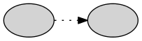
| bold | 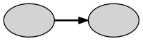 |
Basic style settings for edges
| solid | 
| dashed | 
| dotted | 
| bold |  |
| rounded | 
| filled | 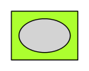
| striped | 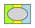 |
Basic style settings for clusters
The effect of style=tapered depends on the penwidth,
dir, arrowhead and arrowtail attributes.
The edge starts with width penwidth and tapers to width 1, in points. The dir attribute
determines whether the tapering goes from tail to head (dir=forward), from head to
tail (dir=forward), from the middle to both the head and tail (dir=both), or no
tapering at all (dir=none). If the dir is not explicitly set, the default for the
graph type is used (see dir). Arrowheads and arrowtails are also drawn, based on the
value of dir; to avoid this, set arrowhead and/or arrowtail to "none".
Note: At present, the tapered style only allows a simple filled polygon.
Additional styles such as dotted or dashed, or multiple colors
supplied via a colorList are ignored.
The following table illustrates the style=tapered with penwidth=7 and
arrowtail=none.
| dir \ arrowhead | normal | none |
| forward | 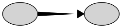 |  |
| back |  | 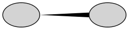 |
| both | 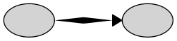 | 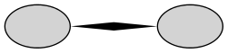 |
| none | 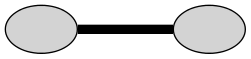 |  |
Additional styles are available in
device-dependent form. Style lists are passed to device drivers, which
can use this to generate appropriate output.
The style attribute affects the basic appearance of nodes, edges and graphs,
but has no effect on any text used in labels. For this, use the fontname, fontsize and fontcolor
attributes, or the <FONT>, <B>, <I>, etc.
elements in HTML-like labels.
The setlinewidth style value can be
used for more control over the width of node borders and edges than is
allowed by bold. This style value takes an argument, specifying the
width of the line in points. For example, style="bold" is
equivalent to style="setlinewidth(2)".
The use of setlinewidth is deprecated; one should use the
penwidth attribute instead.
- viewPort
- "%lf,%lf,%lf,%lf,%lf" or "%lf,%lf,%lf,'%s'"
The viewPort W,H,Z,x,y or W,H,Z,N
specifies a viewport for the final image. The pair (W,H) gives the
dimensions (width and height) of the final image, in
points.
The optional Z is the zoom factor, i.e., the image in the original layout will be
W/Z by H/Z points in size. By default, Z is 1.
The optional last part is either a pair (x,y) giving a position in the original layout of the
graph, in
points, of the center of the viewport, or the name N
of a node whose center should used as the focus.
By default, the focus is the center of the graph bounding box, i.e.,
(bbx/2,bby/2), where "bbx,bby" is the
value of the bounding box attribute bb.
Sample values: 50,50,.5,'2.8 BSD' or 100,100,2,450,300.
The first will take the 100x100 point square centered on the node 2.8 BSD
and scale it down by 0.5, yielding a 50x50 point final image.